TB-4232 · REV D · Technical newsheet
Design EngineeringDevice profile
February 1955: Electronic Design's First 'Ideas for Design' Drew an Oscilloscope Panel Around the Operator
Electronic Design's first Ideas for Design, February 1955, laid out an oscilloscope panel by human-engineering rules: centerline knob placement, a diagonal CRT, and 0.6-inch dial marker spacing.
By Amara Osei3 min read646 words
Features
- The first Ideas for Design article appeared in Electronic Design's February 1955 issue, the magazine's second year.
- The design specifies knob positions on CRT centerlines so rotation direction matches trace motion; vertical control at C, horizontal at D.
- Best relative dial accuracy occurs at roughly 0.6-inch marker spacing, regardless of dial size.
- The IFD series ran in every print issue through the early 2000s and continues online today.
- A diagonally mounted CRT gives an undistorted head-on view even when the scope sits off-center on the bench.
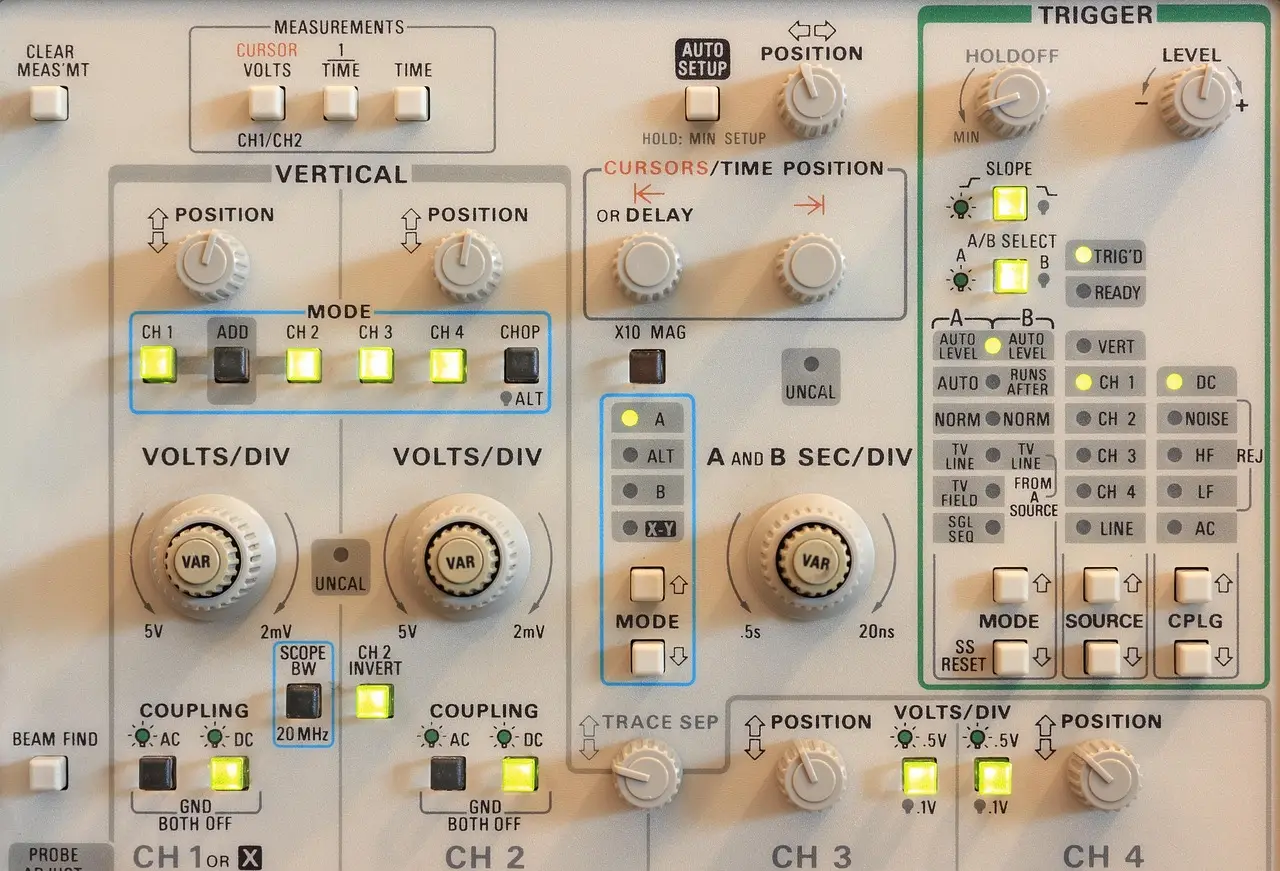
Electronic Design published its very first reader-contributed "Ideas for Design" (IFD) article in the magazine's February 1955 issue — its second year of publication — and the subject was not a circuit but a control panel. The piece proposed a hypothetical oscilloscope front panel laid out according to human engineering principles (what we now call ergonomics or human-factors design), arguing the instrument would be "particularly easy and natural to operate, especially for the operator who would not have used the instrument before." Bill Wong, Senior Content Director at Electronic Design, reintroduced the piece, noting that one or more IFDs typically ran in each print issue through the early 2000s; the publication is now online-only, and the series continues.
What did the 1955 design actually specify?
The anonymous author broke the oscilloscope into two input streams — signal leads from the circuit under observation, and panel controls for frequency, amplification, and position — plus one output: the cathode-ray tube (CRT) display. The organizing rule was that input and output information must be arranged "to operate naturally. That is, to be psychologically acceptable."
The centerpiece is knob geometry around the CRT screen. A vertical centering control placed at position A — directly on the screen's vertical centerline, at the top — means clockwise rotation moves the trace down and counterclockwise moves it up. Place the same knob at C (the bottom centerline position) and the sensed directions reverse. Positions B and D (the horizontal centerline locations) offer no natural rotational direction for a vertical control at all. The horizontal centering control behaves symmetrically: natural at B and D, meaningless at A or C.
The design puts the vertical control at C and the horizontal control at D, chosen so the average right-handed operator's hand never covers the screen during adjustment. Related controls — gain, sensitivity, attenuation — line up beside their respective centering controls, horizontal with horizontal, vertical with vertical. Focus and intensity sit directly on the tube bezel to bind them visually to the CRT. Input jacks run across the panel bottom so leads lie flat on the workbench and cannot be knocked loose. That last detail is quietly excellent. Nobody enjoys re-probing a live circuit.
Why a diagonal tube and 0.6-inch dial spacing?
Two further refinements carry the argument beyond mere tidiness. With the scope on the right side of the bench — "the natural side for note taking by a right-handed observer" — the deliberately asymmetric layout brings the display closer to the user. Better still, the author proposes mounting the tube diagonally in the cabinet, giving the observer a head-on, undistorted view of the screen even when the instrument sits off-center. An off-axis CRT suffers trapezoidal distortion; diagonal mounting, decades before flat displays, was the practical cure.
The knob dials themselves come in three types: Type A, unmarked, for visual positioning while watching the screen; Type B, a knob arrow plus terminal panel markings, for "more or less" relative adjustments; and Type C, a knob arrow with a full set of subdivisions for quantified settings. Selector switches get every position labeled. For continuously adjustable controls the range divides into ten parts, and the author reports an empirical finding: whatever the dial size, the best relative accuracy comes when markers sit about 0.6 inches apart. A number, a method, a claim. Sixty-plus years later, that spacing still looks sane.
The author closed by generalizing: the same principles extend to all electronic devices, and meter faces — easier to mount diagonally or on pivots than CRTs — could adopt the same off-center placement immediately.
Does anyone still buy instruments this way?
Modern scopes bury most of this in menus, which trades one ergonomics problem for another. The takeaway is plain: the first IFD already understood that a measurement instrument is judged by how a human hand and eye use it.
via mwrf.com (Original)
Filed under
- oscilloscope-design
- human-factors
- control-panel-ergonomics
- electronic-instrumentation
- crt-displays
More from Amara Osei
Show full bio
Senior reporter covering people, launches and day-to-day practice in Instruments, test and measurement at Testbench Report.
124 articles
Application notes
- Cavity 3 at 10.045 mm: Why Ticks Fail First Article Reports
- 1,000 Drops From 6 Feet: How REEKON Validated a Digital Tape Measure
- EDN Design Idea Pairs Analog Circuit With Bench Gear to Build Thermometer
- Ranatec Ships Ready-to-Use Switch Boxes for Test Rigs
- Foundrax Packs Automated Brinell Measurement into Handheld Microscope